Diodes
Transistors were originally designed to replace mechanical switches/relays, but also provide amplification. Transitstor/diodes are made by adding impurities to silicon to make it either p-type (hole carriers, positive charge moves) or n-type (electron carriers, negative charge moves). Putting the two together makes a PN-junction, or diode. Diodes only allow current in one direction, as determined by the bias voltage (usually around 0.7v).
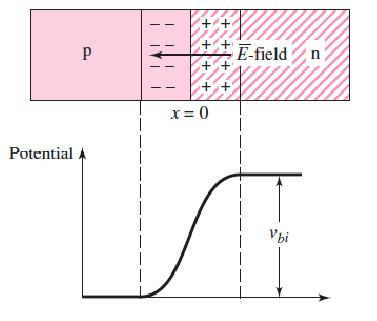
When the PN-junction is forward biased, current flows from P to N.
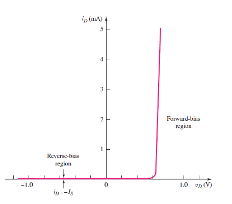
The PN-junction can be reverse biased too, and at a certain point ("the knee"), the bias will break down and current flow in reverse
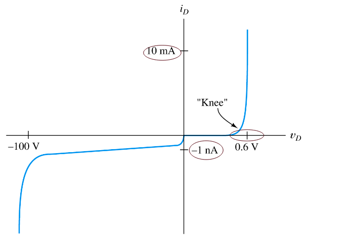
The graph shows a typical small-signal silicon diode at a temperature of 300k. Zener Diodes are diodes where the reverse breakdown voltage is controlled during manufacture to create diodes that act as voltage regulators when reverse biased.
The Shockley equation for a PN-junction related diode current and voltage :
Where I_s is the reverse saturation current, and is the thermal voltage. When v_D is large, typically :
Load Line Analysis
For the circuit below, KVL gives .
The Shockley equation also gives . Equating these gives a transcendental equation with no trivial solution.
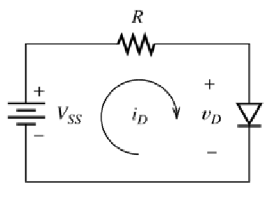
Instead, if an I-V curve is given, can perform load line analysis.
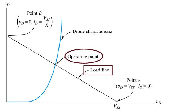
The load line is the straight line from one axis to the other, overlaid with the diode's I-V characteristic curve.
- Point B is a perfect short circuit, ,
- Point A is an open circuit, ,
The operating point, or Q (Quiescent)-point, is the point at which the two lines intersect, giving an operating point of .
If the diode is not conducting, then tiny to zero current flows. Otherwise, it will conduct almost perfectly at about 0.7 volts, so usually.
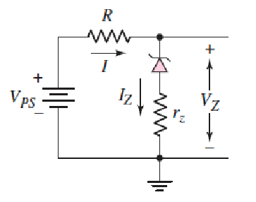
The Zener Diode
Zener diodes are designed to operate in the reverse breakdown region. The breakdown voltage is controlled by the doping level during manufacture, which allows a fixed voltage to appear between cathode and anode (that isn't just 0.7v). The ideal Zener diode behaves something like this:
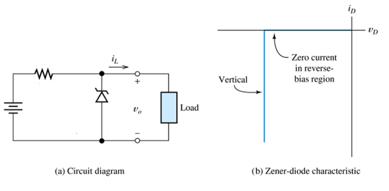
The circuit below shows a diode being used to regulate the voltage of a variable supply, to keep the voltage supply to a load constant
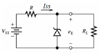
As an example, given a Zener diode's I-V curve, find the output voltage for and , with . KVL gives a load line of :
The graph shows the two load lines plotted with the diode I-V curve, giving of 10V and 10.5V, respectively.
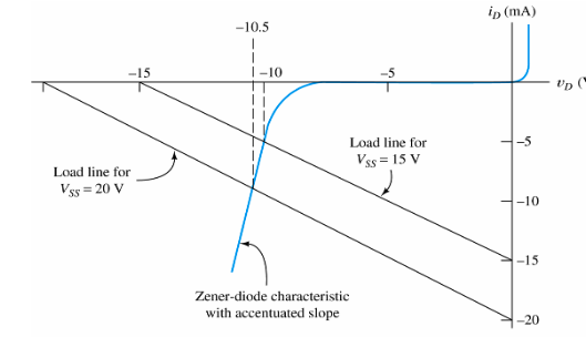
When modelling Zener diodes, an internal resistance is sometimes used, which is what gives the slope of the I-V curve as :