Equations
Below are some of the main equations that I have found useful to have on hand.
Capacitors
Energy Stored
The energy stored by a capacitor of capacitance, C with a voltage, v
- = Capacitance, Farads, F
- = Voltage, Volts, V
- = Charge, Coulombs, C
Capacitor Equation
The ratio of charge to voltage.
- = Capacitance, Farads, F
- = Voltage, Volts, V
- = Charge, Coulombs, C
Capacitance equation
- = the area of the two plates
- = the separation of the two plates
- = the relative electric permittivity of the insulator
- = the permittivity of free space
Series Capacitors
Parallel Capacitors
Current-Voltage
Step Response
- = Voltage of the capacitor at time t, Volts
- = Voltage in, Volts
- = Starting Voltage, Volts
- = Capacitance, Farads, F Derived from:
Electric Field Strength
- = Force
- = Charge
- = Permittivity of free space =
- = Constant
- = Voltage Potential, Volts
- = Separation
Capacitor Reactance
As the capacitor charges or discharges, a current flows through it which is restricted by the internal impedance of the capacitor. This internal impedance is commonly known as Capacitive Reactance
- = Reactance of the Capacitor, Ohmns
- = =
- = frequency, rads per second
Flux Density
The amount of flux passing through a defined area that is perpendicular to the direction of the flux.
Magnetic Field Strength of Straight Current Carrying Wire
Amperes Law: For any closed loop path, the sum of the products of the length elements and the magnetic field in the direction of the length elements is proportional to the electric current enclosed in the loop.
- = Magnetic field strength at distance d
- = Current
- = Permeability of free space =
- = distance from the wire.
Inductors
Inductors in Series
Inductors act in the same way as resistors in terms of their behaviour in series and parallel.
Inductors in Parallel
Induced Voltage
If a coil contains N loops, the induced voltage V is given by the following equation, where Φ is the flux of the circuit.
Self Inductance
A changing current causes a changing field, which then induced an EMF in any conductors in that field, When any current in a coil changes, it induced an EMF in the coil
Energy Stored
The energy stored by an inductor is given by:
Step Response of RL Circuit (Current)
- - Voltage source
- - Resistance of the resistor
- - The initial current. (If is already charged, then will be short circuit current)
Step Response of RL Circuit (Voltage)
Inductor voltage at time t,
- - Voltage across inductor at time t
- - Voltage source
- - Resistance of the resistor
- - The initial current
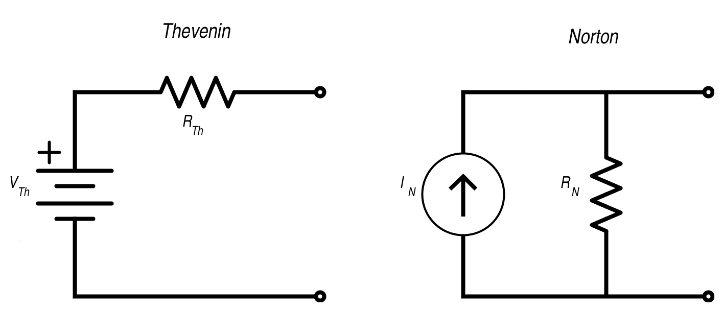
Thevenin and Norton Equivalent Circuits
Thevenin circuits contain a single voltage source and resistor in series. Norton circuits contain a single current source and a resistor in parallel
Equivalent Resistance
Any linear network viewed through 2 terminals is replaced with an equivalent single voltage & resistor.
- The equivalent voltage is equal to the open circuit voltage between the two terminals (/)
- The equivalent resistance () is found by replacing all sources with their internal impedances and then calculating the impedance of the network, as seen by the two terminals.
- This can be done alternatively by calculating the short circuit current (/) between the two terminals, and then using ohms law: .
- The value of the voltage source in a Thevenin circuit is
- The value of the current source in a Norton circuit is
- The value of the resistor in either circuit is
Thevenin - Norton Conversion
Thevenin and Norton are essentially the same, but in a different form. The is the same for both.
- - Norton Current
- - Thevevin Voltage
- - Thevenin Resistance

AC Circuits
- AC current is the dominant form of electricity,
- Current changes direction at a fixed frequency (usually 50~60Hz)
- AC voltage is generated by a rotating electromagnetic field
- The angular velocity of this rotation determines the frequency of the current
Instantaneous Voltage
An instantaneous voltage V in a sine wave is described by
Where:
- is the peak voltage
- is the angular frequency (rad/s)
- is the phase shift (radians)
- The period of the wave is given by
Instantaneous Current
As current and voltage are proportional, AC current is defined in a similar way:
AC Phasor - As complex number
An AC phasor can be represented as a complex number.
Operational Amplifiers
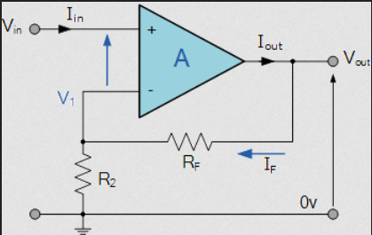
Output of Inverting Amplifier
The gain of the amplifier is set by the ratio of the two resistors. The negative feedback reverses the polarity of the output voltage (Hence Negative).

Output of Non-Inverting Amplifier
Non-inverting amplifiers don't invert the voltage output, and use input at the non-inverting terminal of the op amp instead.

Filters
Cutoff Frequncy
The cutoff frequency of a filter is the point at which the gain is equal to -3 dB, which corresponds to a fall in output by a factor of . For the filter shown above, this is:
Gain (dB)
Gain is measured in decibels
At very low frequencies, the gain is constant (0dB) The capacitor has high reactance at low frequencies, and is open circuit at very low frequencies At very high frequencies, the gain tends towards − dB The capacitor has a very low reactance at high frequencies (short circuit)