Passive Filters
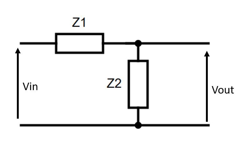
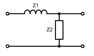
Op amps are active filters because they require power. Passive filters use passive components (Resistors, Inductors, Capacitors) to achieve a similar effect. They are constructed using a potential divider with reactive components. The diagram below shows a potential divider with two impedances, and :
Transfer Functions
The transfer function is the ratio of input to output (see ES197 - Transfer Functions for more details.). For a passive filter, this is the ratio of output voltage to input voltage, as shown above. For a filter, this will be a function of the input waveform, . When and are both identical resistors :
However, if was a capacitor , :
The gain and phase of the output are then the magnitude and argument of the transfer function, respectively:
Cutoff Frequency
Similar to active filters, passive filters also have a cutoff frequency . This is the point at which the power output of the circuit falls by , or the output gain falls by -3dB, a factor of . Using the above example again (a low pass RC filter):
This is also the point at which
The filter bandwith is the range of frequencies that get through the filter. This bandwith is 0 to for low pass filters, or and upwards for high pass.
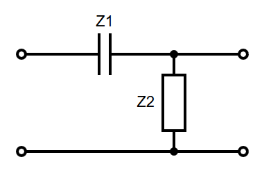
RC High Pass
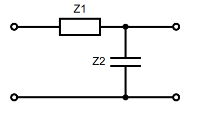
RC Low Pass
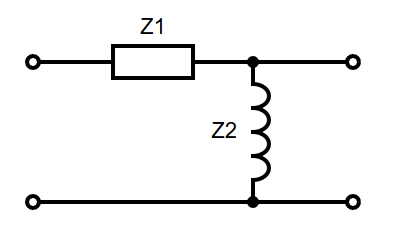
RL High Pass
RL Low Pass
2nd Order Circuits
For circuits more complex than those above, to find the transfer function, either:
- Find a thevenin equivalent circuit, as seen from the element
- Combine multiple elements into single impedances
Note that any of the above techniques only work for simple first order circuits.
Example
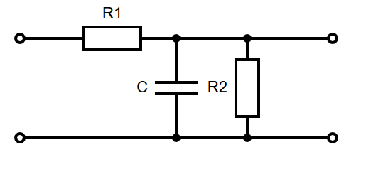
Using , where , and :