BJT Amplifiers
- BJTs make excellent amplifiers when biased in the forward-active region
- Transistors can provide high voltage, current and power gain
- DC biasing stabilises the operating point
- DC Q-point determines
- Small-signal parameters
- Voltage gain
- Input & output impedances
- Power consumption
- DC analysis finds the Q-point
- AC analysis with the small-signal model is used to analyse the amplifier
Hybrid-Pi Model
The hybrid-pi small signal model is what is used for hand analysis of BJTs:
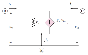
- Intrinsic low-frequency representation of a BJT
- Does not work for RF stuff
- Ignoring output impedance assumes is large
- Parameters are controlled by the Q-point
- Transconductance
- Thermal voltage
- Input resistance
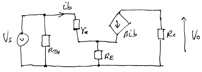
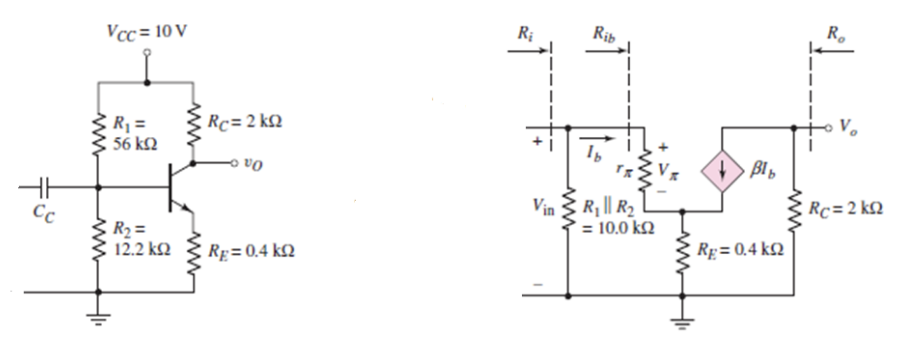
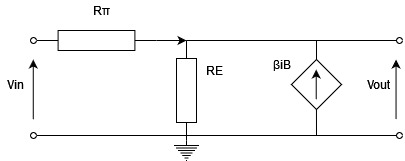
For AC analysis, coupling capacitors are replaced by short circuits, and DC voltages replaced by short circuits to ground. The circuit below shows a 4-resistor bias amplifier replaced by it's small signal model.
AC Analysis
The impdance at the base input :
The impedance at the emitter is reflected back to the base, multiplied by . This makes the overall input impedance of the amplifier:
The output impedance is easy, as lookong into the collector, we can see in parallel with a current source which has infinite impedance, so:
The voltage accross is the output voltage:
The voltage accross is the input voltage:
The overall voltage gain is therefore:
Note that the gain is negative meaning this is an inverting amplifier. If we make the assumption that , and that is large, then:
Common Collector Amplifier
The common collector (or emitter-follower) amplifier is another amplifier circuit used with BJTs (as oppose to the common emitter shown above).
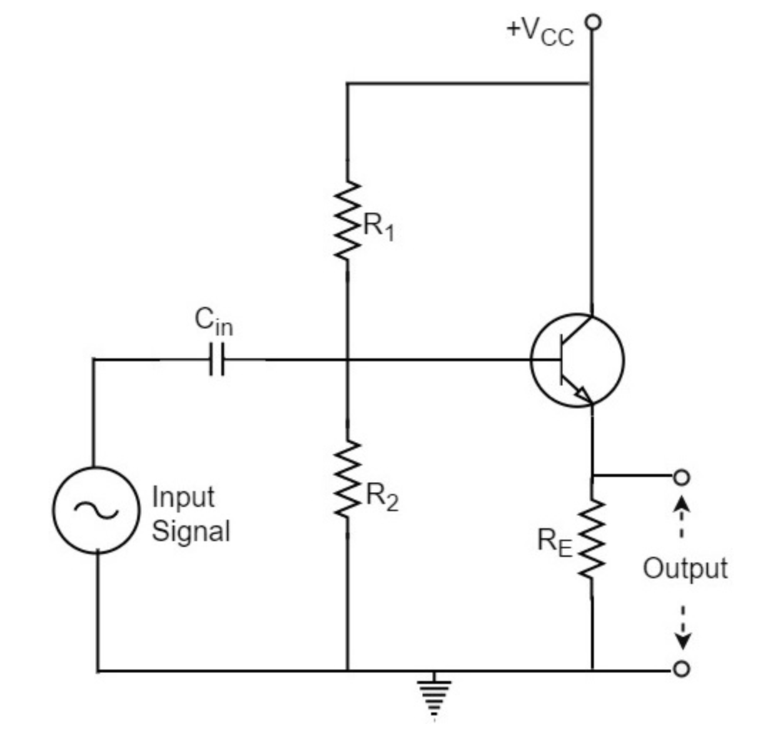
The hybrid-pi model of this circuit looks like, as without the collector the circuit can be re-arranged to:
The output voltage is the voltage accross the emitter resistor, and as :
The input voltage is the voltage accross both the emitter resisitor and :
Therefore the voltage gain for this amplifier is:
As usually, , . This amplifier has very low voltage gain, and instead acts as a current amplifier:
The input impedance is large, as it is the reflected impedance from the emitter resistor again:
The output impedance can be calculate by shorting , and by applying a test current source accross the output terminals. I'm not going to type out all the analysis but:
The emitter follow has high input and low output impedance with a high current gain, so acts as an impedance transformer and a buffer.
Example
A circuit for a common-emitter amplifier is shown below.
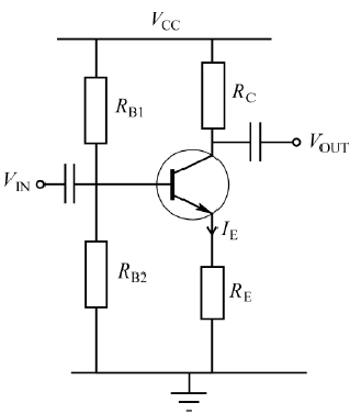
Work out the values of the DC biasing components , , and for the following conditions:
- Voltage accross
Assuming and , we have:
Calculating the Thevenin equivalent of the biasing resistors:
Then calculating the bias resistors from the Thevenin values:
To derive an expression for the voltage gain, need to replace the BJT by it's small signal model