Bipolar Junction Transistors
There are two kinds of BJTs, NPN and PNP. Both have a base, collector, and emitter and consist of two PN-junctions.
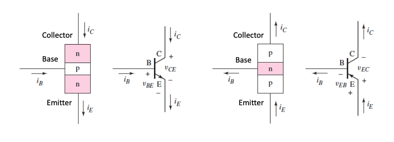
The operating mode of a BJT depends on how the junctions are biased.
- Forward active mode is used for amplification
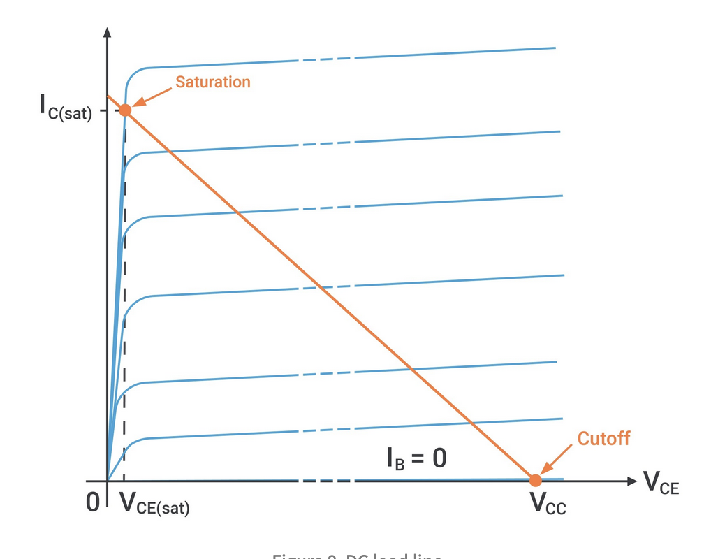
- Cutoff and saturation modes are used for switching in digital circuits
- Cutoff is when both junctions are fully off
- Saturation is when both junctions are fully on
| Mode | Base-Emitter Bias | Collector-Base Bias |
|---|---|---|
| Cutoff | Reverse | Reverse |
| Forward active | Forward | Reverse |
| Saturation | Forward | Forward |
Transistors obey KCL, so all currents entering a transistor must leave:
Transistors also have common-emitter current gain,
There is also the parameter , the common-base current gain:
is usually large, so
Large-Signal Model
BJTs operating in forward-active mode can be modelled as shown:
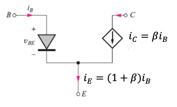
The current source shown is dependant upon the base current, and a diode is included to model the 0.7v drop across the PN-junction. This model assumes the transistor is biased correctly, as shown:
Biasing
Biasing is used to set up quiescent collector current to achieve optimum AC and DC conditions at the same time. is not well specified and can vary per device, so it should be designed to produce the correct operating conditions independent of device parameters and temperature. The Q-point is defined by and .
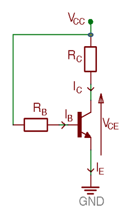
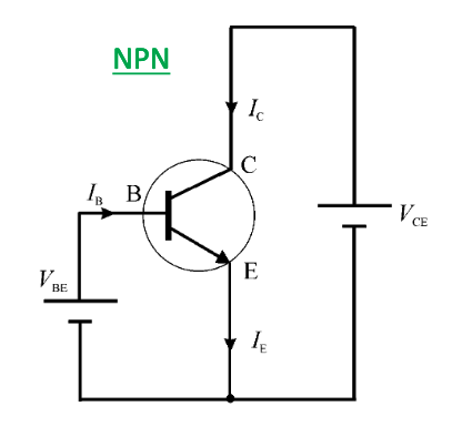
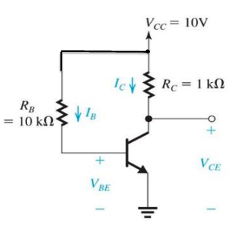
The circuit shows a single resistor base-biased circuit. Doing KVL around the base-emitter loop gives :
KVL between and ground gives :
Equations depending on are bad though, because can vary too much to rely on it as a parameter. The graph below shows the same circuit with the same resistors, as varies:
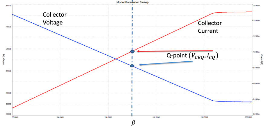
The Q-point shown is for , which gives and
Four-Resistor Voltage Divider Bias
This is the most widely used method to bias a BJT
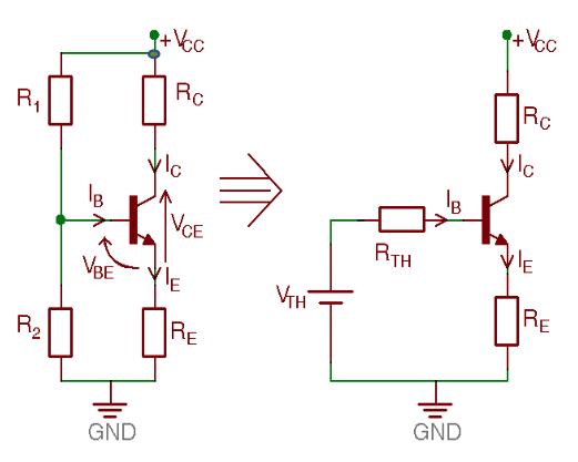
Thevenin's theorem is used to simplify the bias circuit
Applying KVL around the base-emitter loop:
As :
Therefore, the collector current :
Howere, we need to stabilise to not depend upon . If we choose to be small, ie , then we can disregard it along with :
The equation (approximately) no longer depends upon . Applying KVL around the collector-emitter loop for the voltage gives:
So, if is stable, then the Q-point is bias-stable. Stability is achieved through the choice of a small enough, , and also the inclusion of an emitter resistor which provides negative feedback stabilisation.
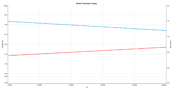
Compare the graph below with the same one further up for the single-resistor bias circuit. The voltage/current are much more stable and less dependant up on .
Transistors in Saturation
This can't be correct. The model breaks down as the transistor is saturated, its no longer operating in the forward-active region.
- The voltage accross the collector/emitter maxes out at about 0.2v
- The transistor then turns on like a switch
- Collector to emitter is (roughly) a short circuit
When operating in saturation, becomes :
This is much lower than a typical would be. As is increased further, decreases further and further.