Power Dividers, Couplers & Resonators
Power dividers divider one input signal into two or more output signals. Power couplers take two or more inputs and combine them into a single output.
Wilkinson Power Divider
The equal split (3dB) Wilkinson power divider will be considered, although it can be designed to give arbitrary power division.
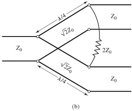
The circuit is formed of two lines of impedance , with a resisitor in shunt accross the two lines of impedance . The scattering parameters:
-
- at port 1, the input
-
- Ports 2 and 3 are matched for even and odd modes of excitation
-
- Symmetry due to reciprocity
-
- Due to short or open circuit at the bisection
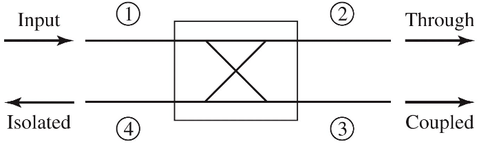
Directional Coupler
A directional coupler is shown below
- Power supplied to port 1 is coupled to port 3
- The coupled port
- The remainder of the input power is delivered to port 2
- The through port
- No power is delivered to port 4
- The isolated port
The quantities used to characterize a directional coupler:
- Coupling factor - the fraction of the input power that is coupled to the output port
- Directivity - a measure of the coupler's ability to isolate forward and backward waves
- Isolation - the measure of the power delivered to the uncoupled port
- Insertion loss - the power delievered to the output port
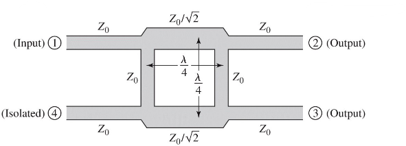
The quadrature hybrid directional coupler is a 3dB directional coupler with all ports matched, and input power divided evenly between ports 2 and 3. No power is coupled to port 4. The coupler is symmetrical, and any port can be used as the input/output ports.
Resonators
RLC Resonators
Resonators at microwave frequency are similar to lumped element RLC circuits:
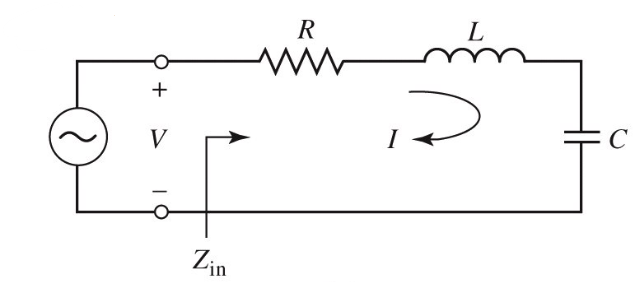
Input impedance:
Power delivered:
The resistors dissipates power , while the inductor and capacitor store energy and :
At the resonant frequency of , and
The quality factor of a resonant circuit is defined as the ratio of energy stored to energy loss:
measures the loss of the circuit: higher Q means higher loss. An external connecting network may introduce additional loss, so the of the resonator itself (the unloaded ) is:
The input impedance of the series resonator at a frequency , where is small:
A lossy resonator can be modelled as a lossless resonant frequency replaced by a complex effective resonant frequency .
When the frequency is such that , the real power delivered to the circuit is half that as of at . We use this to define the fractional bandwith as .
The same analysis can be done for a parallel RLC resonator. The properties of the two are compared in the table below
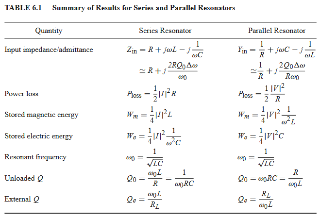
In general, resonators are coupled to other circuitry which gives a loaded . If we couple a resonant circuit to an external load and define , the external load, then:
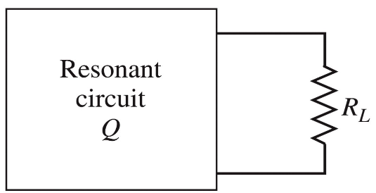
For a series RLC resonator, effective resistance is , and . In parallel, effective resistance is and
Transmission Line Resonators
Open Circuit line
A practical resonator that is often used in microstrip circuits is an open circuit length of transmission line of length , which behaves as a parallel resonator circuit. The input impedance is:
In practice, low loss transmission lines are used, so we can approximate . Using again for small near to the resonant frequency, we have:
At resonance, , the unloaded of this resonator is:
Gap-Coupled Microstrip Resonator
Consider a open-circuit microstrip gap-coupled to the end of a microstrip transmission line. The normalised input impedance is:
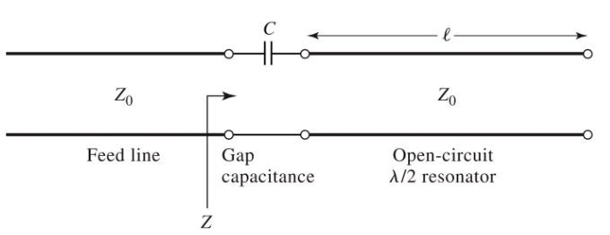
The resonant frequency occurs when , ie when
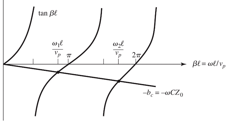
The first resonant frequency is close to the resonant frequency of the unloaded resonator, so we have . The coupling of the resonator to the feedline has the effect of lowering it's resonant frequency.
The presence of a coupling capacitor turns the uncoupled line from a parallel to a series RLC circuit near resonance. At resonance:
For critical coupling, :