Network Parameters
Impedance & Admittance Parameters
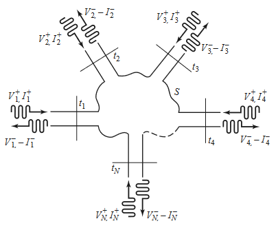
- Consider an N-port microwave network
- Forward and backward voltage and current waves can be defined for TEM waves
- Can define matrices of impedances(/admittances) to relate voltage and current port parameters to each other
- Ports may be any type of transmission line for a single propagating mode
- At a specified point on the port, a terminal place is defined
- Terminal planes provide a phase reference for wave phasors
- Equivalent incident and reflected voltage and current also defined
- At the terminal, total voltage and current are given by
- Assumes coordinate along which propagation occurs is zero at terminal
The impedance matrix relates these voltages and currents:
Can similarly define an admittance matrix
The two matrices are inverses of each other: . Both matrices relate total port voltages and currents.
can be found by driving port with current , open circuiting all other ports, and measuring the open circuit voltage at port
is the input impedance looking into port , and is the transfer impedance between ports and .
The admittance matrix parameters are found similarly:
- If a network is reciprocal (contains no active devices), then the matrix is symmetric
- For a reciprocal lossless network, all the or elements are purely imaginary
- for any and
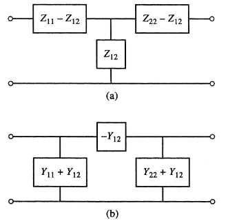
Any two port network can be reduced to an equivalent or network:
Scattering Parameters
- Direct measurements of voltage and current become not that useful at high frequency because of waves
- The scattering matrix representation is more in line with the direct measurement of waves
- Provides a complete description of an -port network, relating incident and reflected waves on ports.
The S-matrix is defined
is found by sending port an incident wave and measuring at port the reflected amplitude . The incident waves on the rest of the ports are set to 0, meaning all ports are terminated in matched loads to avoid reflections.
- is the reflection coefficient looking into port
- is the transmission coefficient (gain) from port to
- The scattering matrix for a reciprocal network is symmetric
- The scattering matrix fro a lossless network is unitary
- Identity
Shifting Reference Planes
In the original network, the terminal planes are assumed to be at , where is measured along the lossless line feeding the port. The matrix with this set of planes is . If the new reference planes are defined , then we get a new scattering matrix defined . From travelling waves on a lossless line:
We can use this shift to define in terms of
Transmission (ABCD) Parameters
Practical microwave networks consist of a cascade connection of two or more 2-port networks. It is useful to define a 2x2 transmission, or ABCD matrix, for each 2-port network such that the transmission matrix of the cascade connection can be obtained as the product of the transmission matrices of the individual networks.

Note the sign convention, which has flowing into port 1, and flowing out of port 2.
If two networks are cascaded, ie network 1 outputs into network 2, the transmission matrix of the cascaded network is the product of the two individually
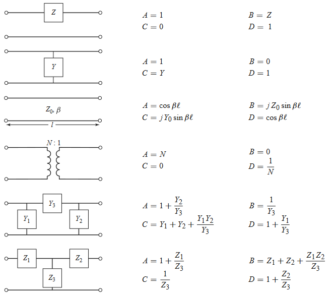
Some useful ABCD parameters for common networks are shown below
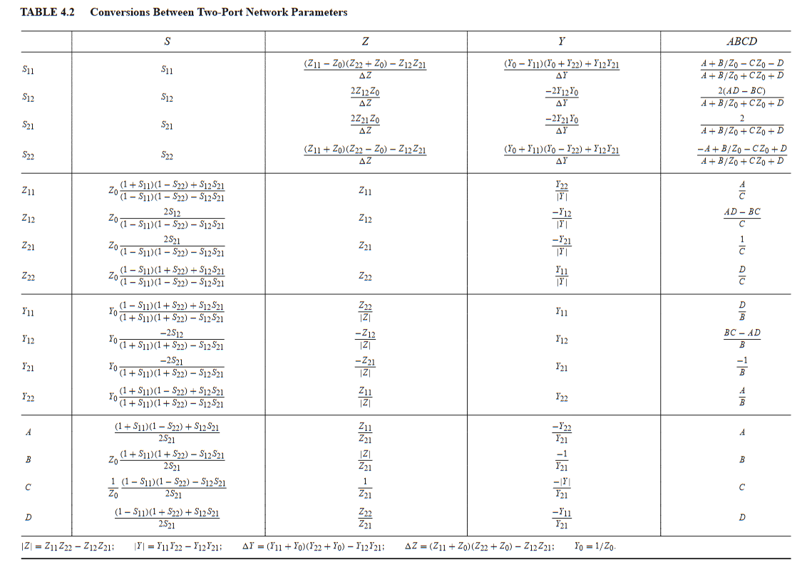
Port Parameter Conversion Table