Transmission Lines
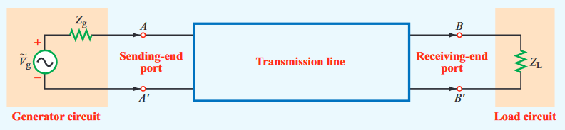
A transmission line is a two port network that connects a source to a load
Modes
- Modes descibe the field pattern of propogating waves
- Can be found by solving Maxwell's equations in a transmission line
- In a transmission line, electric and magnetic fields are orthogonal to each other, and both orthogonal to the direction of propogation
- This is TEM (Transverse Electromagnetic) mode
- A TEM transmission line is represented by two parallel wires
- To reason about voltages and currents within it, we divide it into differential sections
- Each section is represented by an equivalent lumped element circuit
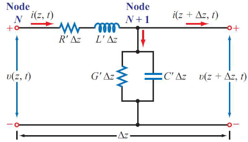
- - the combined resistance of both conductors per unit length, in
- - the combined inductance of both conductors per unit length, in
- - the combined capacitance of both conductors per unit length, in
- - the conductance of the insulation medium between the two conductors per unit length, in
The table below gives parameters for some common transmission lines
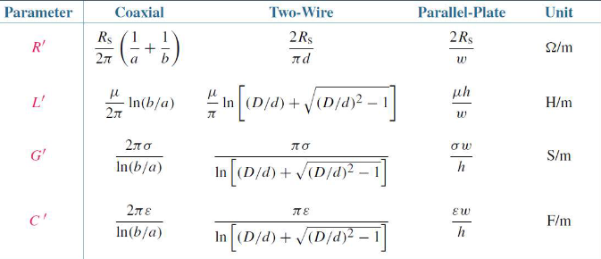
- Conductors have magnetic permeability and conductivity
- The insulating/spacing material has permittivity , permeability and conductivity
- All TEM transmission lines share the relations
- The constant propogation constant of a line
- is the attenuation constant (Np/m)
- is the phase constant (rad/m)
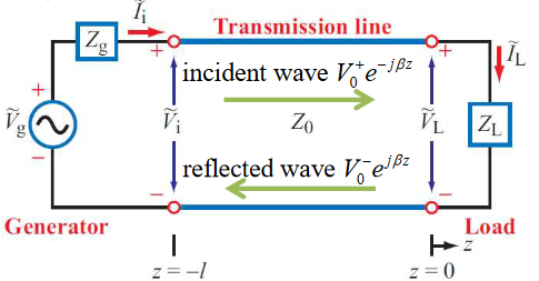
- The travelling wave solutions of a line are
- represents position along th eline
- represents the incident wave from source to load
- represents the reflected wave from load to source
We therefore have the characterisitic impedance of the TEM transmission line:
Both the voltage and current waves propagate with a phase velocity . The presence of the two waves propagating in opposite directions produces a standing wave.
The Lossless Transmission Line
In most practical situations, we can assume a transmission line to be lossless:
- , and
- Assume , so
- Therefore, as :
This then gives velocity and wavelength:
As the insulating material is usually non-magnetic, we have
Voltage Reflection Coefficient
Assume a transmission line in which the signals are produced by a generator with impedance and is terminated by a load impedance .
At any position on the line, the total voltage and current is:
At the load at position , the load impedance is:
Using this we can find an expression for the ratio of backwards wave amplitude and forward wave amplitude. We obtain the equation below, the voltage reflection coefficient
- for a lossless line is a real number, but may be a complex quantity
- In general, the reflection coefficient is also complex,
- Note that , always
- A load is matched to a line when , as then
- No reflection by the load
- If then , then
- Open circuit load
- If then , then
- Short circuit load
Standing Waves
The standing wave equation gives an expression for the standing wave voltage at position
The ratio of to is called the Voltage Standing Wave Ratio, or VSWR. Max occurs when , and min occurs when
Input Impedance of Lossless Lines
The input impedance of a transmission line is the ratio of the total voltage to the total current at any point on the line
- For a short circuit line ,
- For an open circuit line ,