FPGA Arithmetic
FPGAs demonstrate their power specifically in applications that require complex computation at high data throughput, so the specifics of how arithmetic is carried out is important.
Number Format
- The binary number format is positional
- The value of a binary number is the sum of each element multiplied by it's position
- The rightmost bit is the LSB
- Leftmost bit is MSB
- Bits are indexed by their power
- LSB is bit 0
- MSB is bit n-1
- The range of an unsigned n-bit number is
- Sign-magnitude can be used to represent signed numbers
- An offset can also be used, where the number range is shifted by an amount
- Two's complement is mostly used where the MSB has a negative weight
- To negate a number, invert the bits and add 1
- If MSB = 1, the number is negative
- Has range to
- To widen a two's complement number, you need to sign extend
- Add more bits to the left with the same value as the current sign bit
Adders
The full adder allows to carry out a full add operation on two operands, producing a sum and carry ouput. This can be extended into a ripple adder, which is multiple adders chained together to create multi-bit adders.
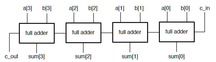
- Carry bits are passed up the chain from LSB to MSB
- The carry ripples through the circuit
- We have to wait for all the carry bits to propagate through the circuit to get the correct result
- Not efficient
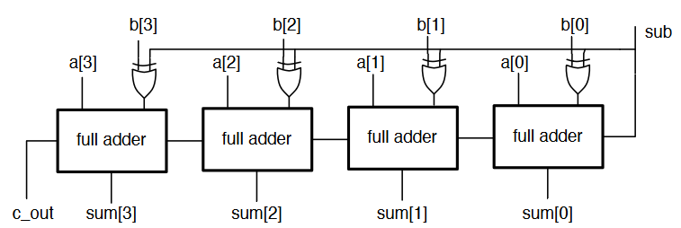
The ripple adder can also be adapted to be able to subtract using XOR gates, and by adding one using the input carry bit.
- In a synchronous system, we place the operands in registers and sum the registers
- The speed at which we can run the clock to update the registers depends on the propagation delay of the adder
- Can only clock the circuit as fast as the critical path allows
- In an adder, this is the carry from LSB to MSB
- Wider adders lengthen this period
Carry-Lookahead Adders
- A bit position generates a carry if it produces a carry, no matter what the carry in to that stage is
- A bit position propagates a carry if it produces a carry whenever it's carry is high
- This can be expressed as logical expressions
- The carry out of bit position is
- Also,
- The carry of each bit position can be expressed in terms of the previous ones
- At each stage, the sum, generate, and propagate can be computed
- This allows us to compute any intermediate carry bit
- Since and signals depend only on and , there is no more ripple
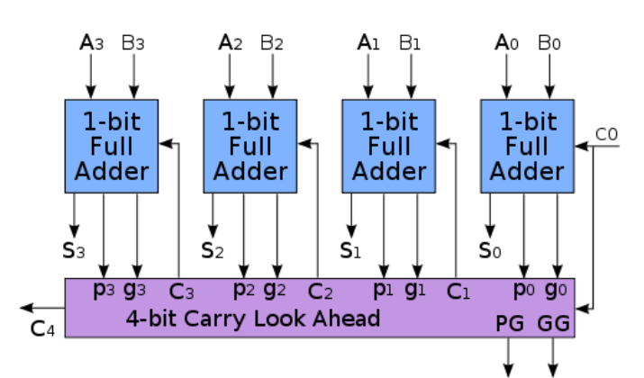
- Several can be chained to implement a much wider adder
- Wider lookahead require much more gates
- Instead of building wider adders from just gates, larger adders can be built up hierarchically from smaller adders (the and output signals are chained)
Other techniques for fast adders include carry-skip adders, which allow carries to skip over bits, and the Manchester carry chain, which uses shared logic for lookahead
Multipliers
- Binary multiplication is done similar to decimal long multiplication
- Multiplication between two bits is an and operation
- After each multiplication stage, one of the operands is shifted
- Partial products as the product of each pair of bits in each shift position are generated
- These partial products are then all summed
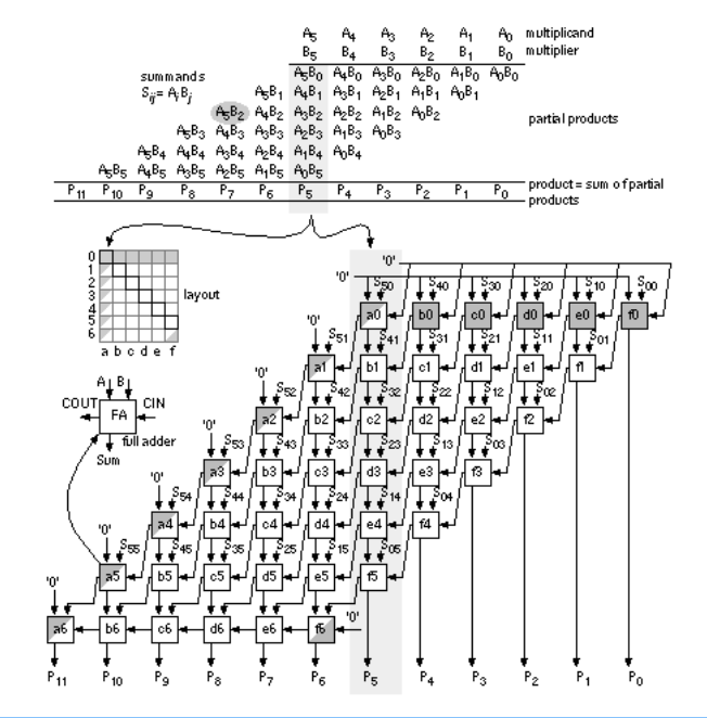
- Alternative architectures try to reduce the amount of addition, eg the Wallace multiplier
- FPGA tools take care of implementing multipliers efficiently using LUTs
- Wider multipliers are mapped to DSP blocks
- Very wide ones might use multiple DSPs
Fixed Point Arithmetic
Fixed point notation allows us to work with fractional numbers.
- Place a binary point at any location within the number
- Arithmetic is performed as integers
- The location of the binary point is kept track of
- Designer can select a precision suited to the application
The only difference when calculating a fixed point value is that some numbers have a weight that is a negative power of two, ie with a fixed point in the middle is .
-
The binary number now consists of two parts
- The integer part determines the range
- The fractional part determines the precision
-
Choosing a different position for the point allows trading accuracy for range
- 4 integer bits gives a range of 0-15
- 6 fractional bits can represent values with a precision of up to
-
There is no fixed notation for stating the position of a binary point, so it is important to be clear
- An bit fixed point number with fractional bits has integer bits
- If the number is signed, the first bit also has negative weight
-
Not all numbers can be represented exactly in a given fixed point format
- This causes some error, but selecting an appropriate precision for the use case can make this tolerable
- True also for floating point
Fixed Point Conversion
The easiest way to convert a fractional number to a given fixed point format is as follows:
- Multiply the number by where is the number of fractional bits
- Round the result to an integer
- Convert the integer to binary in the standard way
- Use the binary representation of that number as the fixed point representation
- Remember where the position of the binary point is for the calculation
For example, convert 2.384 to an 8 bit number with 6 fractional bits
- is the fixed point approximation
- is the actual value of the approximation
- The error is 0.006625 absolute or 0.28% relative
- Probably fine, depending upon the design
When converting, there are some things to watch out for:
- Need to maintain the same binary point position for all values
- If the converted number exceeds the width of the format then integer bits are lost
- Always work out the max integer width and precision you need first based on expected integer range
- When numbers are signed, the MSB has negative weight
Arithmetic affects the binary point:
- Addition and subtraction don't change the position, but an extra bit may be needed to prevent overflow
- Multiplication of an bit number with fractional bits and a but number with fractional bits yields an bit number with fractional bits
- It is important to keep track of where integer and fractional parts are in circuits
Fixed Point in Verilog
Verilog has no native support for fixed point, so the designer must keep track of the positions within the code. Vector slicing is used to choose the required bits. The module below multiplies two numbers with 4 integer and 12 fractional bits.
module mul_short(input signed [15:0] a,b, output signed [11:0] prod)
wire signed [31:0] x = a * b; //wider to prevent result being truncated
assign prod = x[31:20];
All verilog signals are treated as unsigned numbers by default, and we can use built in arithmetic operators on them.
Signed Arithmetic in Verilog
Any reg or wire is considered unsigned, unless it is declared as a signed signal
wire signed [3:0] x;
wire signed [15:0] y;
Signals like this are considered signed, and the design tools take care of generating signed circuits. For signed operations, all operands must be declared singed or verilog will default back to unsigned arithmetic. Signals can be cast using signed() and unsigned() functions
A basic 4-bit signed adder:
module add_signed(input signed [2:0] a,b, output signed [3:0] sum);
assign sum = a+b;
endmodule
A 3-bit signed adder with a carry out will be generated, and any sign-extension is done automatically.
Signed literals can also be used
reg signed [15:0] count_limit = -16’d47
reg signed [7:0] bits_left = 8’d12
When using unsigned vectors, verilog will automatically zero-extend when needed, which is bad for signed numbers. When declaring signals as being signed, verilog automatically sign-extends instead.
reg signed [15:0] x = 8'b1001_1111;
//results in x= 1111_1111_1001_1111
To mix signed and unsigned numbers, it is important to manually cast unsigned to signed:
module add_signed(input signed [2:0] a,b, input carry_in, output signed [3:0] sum);
assign sum = a + b + \$signed({1'b0, carry_in});
endmodule
carry_inis casted so signed circuitry is generated- It is extended with a
0because just casting a single bit to signed would result in a-1- This is important to do to prevent numbers becoming negative
A signed number can be truncated to narrow it's width, but only safely when the upper bits are all the same as the new MSB:
11110101safely truncates to10101(-11)000000011100safely truncates to011100(28)
Verilog will always truncate MSBs as needed if not careful, so care must always be taken when working with signed arithmetic
- Look out for synthesis warnings
- Make internal signals as wide as needed then truncate at the output
Floating Point
- Floating point allows to represent fractional numbers with an adjustable scale
- 32 bits are decomposed into separate fields that make up a number
| Sign | Exponent | Mantissa |
|---|---|---|
| 1 bit | 8 bits | 23 bits |
- Can represent numbers as small as and as large as
- Not all numbers can be accurately represented
- The exponent determines which powers of two the window of values covers
- The mantissa determines where within the window the value is
- As the size of the window increases, the less accurate the values can be
- Floating point circuits are large and complicated
- Not supported in most synthesis tools
- IP blocks are provided for floating point computation, but it should be considered how necessary it is before use