Verification
Testbenches
Testing by loading to the FPGA takes ages. Testbenches allow for easier verifying correctness of verilog designs.
- Algorithmic verification: is the selected algorithm suitable for the desired application?
- Functional verification: does the designed architecture correctly implement the algorithm?
- Synthesis verification: is the design fully synthesisable and implementable on the target design platform?
- Timing verification: once synthesised, placed, and routed, does it meet timing constraints?
Sources of error in design
- The specification may be incorrect or incomplete
- Even if it meets specification, it may not function as intended
- Specification may have been misunderstood
- What has been implemented matches what you think the specification means, not what it actually means
- Specification has been implemented incorrectly
- Errors in code
Most of our time will be spent in functional verification.
- Does design perform all functions in spec?
- Are all required features implemented?
- Does it handle corner/edge cases?
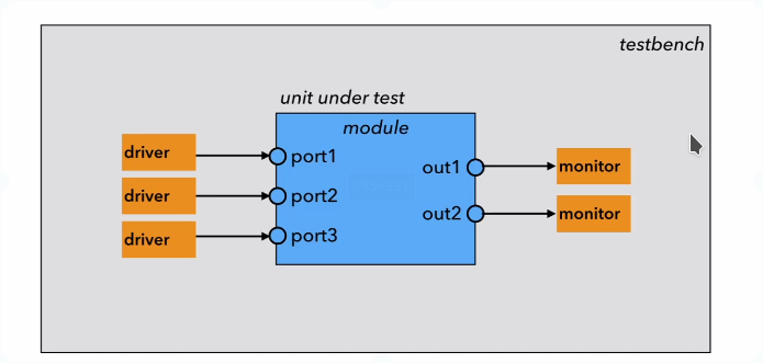
What is a testbench?
- A self contained module, with no inputs or outputs
- Instantiates the unit under test (UUT) - the module we want to verify
- Contains a number of blocks
- Clock generator for driving synchronous elements
- Data and control signal generators for mimicking circuit inputs
- Data and status signal monitors for checking outputs match spec
If the module under test gives correct results when given inputs, then we can assume that it works.
In verilog, a testbench is just a normal module with no ports:
module testbench;
    //testbench statements
endmodule
The inputs to our unit under test will be driven by the testbench and must be declared as reg signals. Outputs must be declared wire. Inputs and outputs are then connected to the instanted module to be tested.
Initial Block
- Another type of procedural block used in testbenches only
- Cannot be synthesised
- Runs concurrently with always blocks
- Used to initialise values when system first starts up
- Can also set values with delay using
#10 a = 1'b1;statements- This tells the simulator to wait 10 time steps and then set a to 1
- Delays are only for simulation and cannot be synthesised
display
- The simulator has a console where the simulator prints messages
- The
displaytask/function allows us to print info to the console - Allows for C-style format strings
- Argument can be an expression also
Verifying Combinational Modules
We want to verify a simple combinational module that computes y = abc + a'bc' + ab'c'. Manually stimulate the inputs to cover all 8 possible input values:
module simplecomb(input a,b,c, output y);
assign y = abc + a'bc' + ab'c';
endmodule

module comb_test();

reg at,bt,ct;
wire yt;
simplecomb uut(.a(at),.b(bt),.c(ct));

initial begin
    at = 1'b0;
    bt = 1'b0;
    ct = 1'b0;

    //increment every 10 time steps
    #10 ct = 1'b1;
    #10 bt = 1'b1; ct = 1'b0;
    #10 ct = 1'b1;
    #10 at = 1'b1; bt = 1'b0;  ct = 1'b0;
    #10 ct = 1'b1;
    #10 bt = 1'b1; ct = 1'b0;
    #10 ct = 1'b1;

    #10 \$finish;
end
endmodule
- Unit under test is instantiated, connecting ports to signals
- Start with input values for
a, b, cof 000 - Wait 10 timesteps and change inputs to
001 - Continue cycling through all possible values
\$finishterminates simulation- We want to see what output waveform is generated by the module so we can verify it exhibits the correct behaviour
Checking the waveform manually is tedious, so we can instead add assertions into testbench to \$display an error if the output does not match the expected value
at = 1'b0; bt = 1'b0; ct = 1'b0;
if(yt != 1'b0) \$display("000 failed")
//.. and so on
This is still tedious, as we still have to work out the correct value in advance. We could carry out the verification using verilog's language features instead:
always #10
    if (yt != (a&b&c | (!a)&b&(!c) | a&(!b)&(!c)))
        \$display("testbench failed for %b %b %b",a,b,c);
In testbench design we can be much more relaxed about using language constructs:
initialis not synthesisable but is fine in testbenches- Delays on assignments can be used
- Assigning to a signal from multiple blocks is not an issue
Testbenches are not designed to be turned into circuits: they are software, not hardware.
Synchronous Verification
- For synchronous testbenches, we need a clock input to oscillate between 0 and 1
- Initial value (high or low) is important and can be done either way
- Verilog below sets clock to change on each timestep (50% duty cycle)
initial clk = 0;
always #1 clk = ~clk;
Timing in Testbenches
- So far, we have assumed dimensionless time
- We can specify the time dimensions
timescale 1ns / 100ps- This line is placed at the top of the testbench source file
- Specifies unit time is
1ns - Specifies max rounding precision to be
100ps#10/8would give 1.2, not 1.25
- Most simulation tools require the timescale to be stated in order to simulate
- During functional simulation this means nothing since timing is not factored in
Since for most designs, clock and reset behaviour is the same, we can use a standard template:
module sync_test;

reg clk, rst;

initial begin
    \$display("Start of Simulation");
    clk = 1'b0;
    rest = 1'b1;
    #10 rest = 1'b0
end

always #5 clk = ~clk;

endmodule
Reset is held high for 10 time steps, then brought down to enable circuit. Clock oscillates continually.
Accessing files
- The set of inputs driving the circuit is a test vector
- Creating test vectors within a testbench is generally only feasible for simple parts of a circuit
- It is also possible to access test data stored in external files
- Allows us to prepare more complex types of test data, eg images
- Can also store simulation outputs in an external file
- Allows for analysis using more suitable tools, eg scripting with matlab/python
- File I/O in verilog is very similar to C
- Need a file handle (stored as an
integer) - Can use read/write/append mode
r/w/a
- Need a file handle (stored as an
- A self-checking testbench can be constructed by reading a set of inputs and outputs from files, and seeing if the unit under test matches them
integer infile;
infile = \$fopen("inputfile.txt","r");
while (!\$feof(infile)) begin
@(posedge clk);
\$fscanf(infile,"%h","%b\n",data,mode);
end
This example reads one hex and one binary value on each line of a test file in each clock cycle, and assigns them to the data and mode signals.
Advanced Verification
- When working with testbenches, should always use the same clock throughout
- If driving an input reg signal on one clock, that data will only enter the module at the next rising edge
- Simple combinational circuits can be tested using counters and inspection of outputs
- For more complex circuits, prepare test data and load from/write to files
\$randomfunction generates a 32-bit random number and can be used for random testing- If there are too many input possibilities, focus on edge cases or cases more likely to cause error
- Finite state machines are nicely decomposed for testing
- Test combinational state transition logic separately
- Test the whole state machine, manipulating inputs.
- Testing process should be iterative and integrated.
How to verify
- Start with a good design specification
- Prototyping is important: develop a prototype first
- Software models can be constructed of at various levels
- Simple model with no reflection of hardware design
- Model that mimics overall functional architecture
- A cycle-accurate model
- A bit-accurate model
- Mode detailed models give a better reflection of the hardware, but take longer to develop (and can have more bugs)
- A functionally correct circuit should produce the same results as a software model of the function, however some discrepancies may still be present
- Number representation can cause differences
- May use different calculation methods
- Can take shortcuts or refactor parts of an algorithm to simplify implementation in hardware
- Should be aware of these discrepancies and know when it is safe to ignore them
- Can apply the same set of input vectors to the hardware design and software model and compare the outputs
- Can also implement the inverse function in software
- Run data through hardware module
- Put outputs into software inverse
- If software inverse outputs original hardware inputs, design is correct
Simulation Environments
- Vivado comes with simulator built in
- Waveform window shows signals in design
- Signal values plotted as wave over time
- Useful for debugging
- More complex designs require more complex verification techniques
Modern Verification
- There have been many recent developments in electronic design automation around verification
- SystemVerilog adds new verification features
- Formal mathematical circuit verification involved proving a design is correct
- Sources of error can occur in places other than the design
- Faulty specification
- Buggy tools
Consider a large multiprocessor SoC:
- Test each processor and all layers in a hierarchy
- Test communication and interfaces
- Test contention for resources
- Test different clocks for different units
- Predict effects of cache misses and race conditions
For simple systems we work with:
- Prepare a software model
- Construct testbenches for simple logic
- Use self-checking testbenches if possible
- Use external files for test data if appropriate
- Make testing an iterative process
Testing can and should consume most of your time!